
Screw Measurements Guide ー Article Plan (as of 03/27/2026 15:46:40)
This guide details crucial screw inspection methods, emphasizing thread gauges for precise dimensional control in today’s manufacturing landscape, ensuring quality parts.
Accurate screw measurement is fundamental for assembly integrity and product performance, demanding careful inspection of threaded components across diverse industrial applications and processes.
Importance of Accurate Screw Measurement
Precise screw measurement is paramount to ensuring the reliability and functionality of assembled products. Incorrectly sized or threaded screws can lead to joint failure, reduced structural integrity, and ultimately, product malfunction. In demanding manufacturing environments, consistent quality control relies heavily on accurate inspection techniques.
Beyond preventing immediate failures, accurate measurements contribute to extended product lifespan and reduced maintenance costs. Utilizing the correct thread gauges and measurement tools minimizes the risk of stripping, cross-threading, and other issues that compromise performance. This diligence is especially critical in industries where safety and precision are non-negotiable, such as aerospace, automotive, and medical device manufacturing.
Applications Across Industries
The need for accurate screw measurement spans a vast range of industries. In the aerospace sector, precise fastener dimensions are critical for structural integrity and flight safety, demanding rigorous inspection protocols. The automotive industry relies on consistent screw sizing for engine components, chassis assembly, and safety systems, preventing costly recalls and ensuring vehicle performance.
Medical device manufacturing requires exceptionally tight tolerances in screw measurements, as even minor deviations can impact device functionality and patient safety. Furthermore, industries like electronics, construction, and general manufacturing all benefit from reliable screw inspection, guaranteeing product quality and minimizing assembly issues. Proper thread gauging, therefore, is universally vital for maintaining high standards.
Understanding Screw Thread Terminology
Key terms like major diameter, minor diameter, pitch, lead, and thread angle define screw threads, enabling accurate measurement and proper gauge selection.
Major Diameter
The major diameter represents the largest diameter of the screw thread, essentially measuring across the outer points of the threads. It’s the dimension specified in screw thread designations, like M6 or 1/4-20, and is crucial for determining compatibility with nuts and tapped holes. Accurate measurement of the major diameter is fundamental during inspection, often performed using calipers or micrometers.
This measurement directly impacts the screw’s ability to engage correctly with mating components. Variations outside acceptable tolerances can lead to assembly issues, reduced clamping force, or even complete failure. Therefore, precise determination of the major diameter is a cornerstone of quality control in threaded fastener manufacturing and assembly processes. It’s the primary reference point for many other thread measurements.
Minor Diameter
The minor diameter, also known as the root diameter, is the smallest diameter of the screw thread, measured at the bottom of the grooves between the threads. Unlike the major diameter which dictates external fit, the minor diameter is critical for assessing thread strength and stress distribution. It’s a less frequently measured dimension than the major diameter, but equally important for ensuring structural integrity.
Measuring the minor diameter often requires specialized tools like internal micrometers or sophisticated gauging techniques. Variations in the minor diameter can indicate wear, manufacturing defects, or improper forming of the threads. A reduced minor diameter weakens the thread, potentially leading to stripping or breakage under load. Maintaining the correct minor diameter is vital for reliable performance.
Pitch & Lead
Pitch defines the distance between adjacent thread crests, measured parallel to the screw axis. It’s a fundamental characteristic determining how quickly a screw advances. Lead, however, is the axial distance the screw travels with one complete revolution. For single-start threads, pitch and lead are identical; Multi-start threads, featuring multiple helical paths, have a lead that’s a multiple of the pitch.
Accurate pitch and lead measurements are crucial for proper fastener engagement and functionality. Incorrect values can lead to binding, misalignment, or insufficient clamping force. Pitch is commonly measured using pitch gauges or by dividing the distance traveled by the number of revolutions. Lead is particularly important in applications requiring precise linear motion, like lead screws in machinery.
Thread Angle
Thread angle, typically denoted as the ‘helix angle’, is the angle between the thread and a plane perpendicular to the screw axis. This angle significantly impacts the screw’s strength, self-locking ability, and load-carrying capacity. Common thread forms, like the 60-degree V-thread used in Unified and Metric screws, dictate a specific angle for optimal performance.
Measuring thread angle accurately is vital for ensuring compatibility and preventing failures. While not directly measured with simple tools, it’s inherent in the thread form and verified through thread gauges and advanced measurement techniques like optical comparators. A deviation from the standard angle can compromise the screw’s integrity and lead to stripping or reduced clamping force. Maintaining the correct angle is paramount for reliable fastening.
Common Screw Measurement Tools
Essential tools include calipers (vernier and digital), micrometers (external, internal, depth), and thread gauges (go/no-go) for precise screw dimension verification.
Calipers (Vernier & Digital)
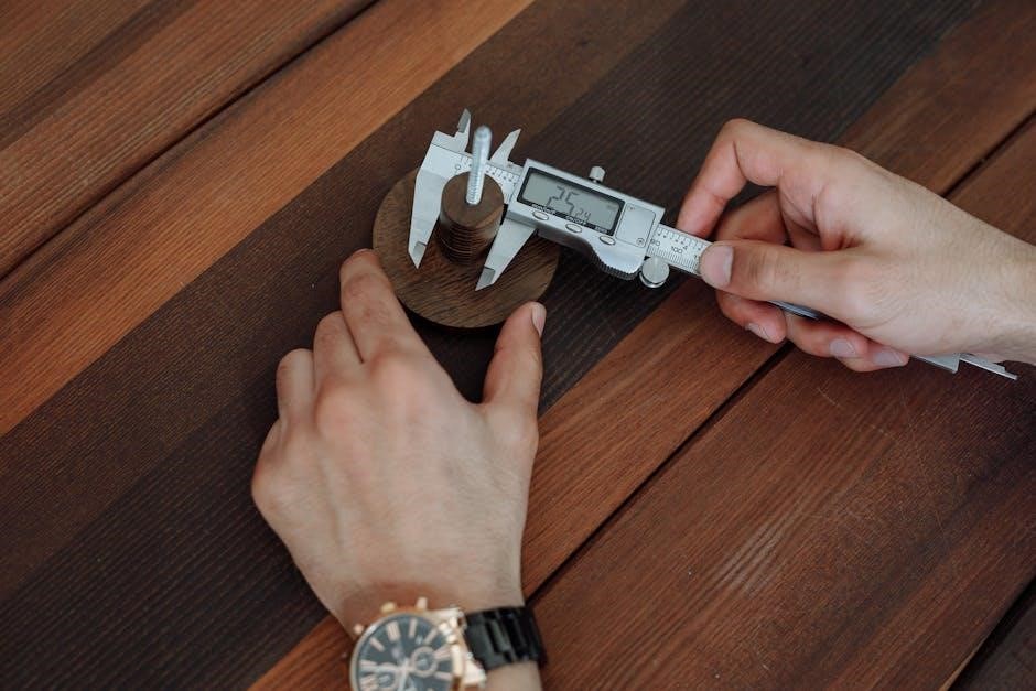
Calipers are versatile tools for measuring screw dimensions, available in both vernier and digital formats. Vernier calipers utilize a main scale and a vernier scale, requiring skilled interpretation for accurate readings. They offer high precision but can be prone to parallax errors.
Digital calipers, conversely, provide a clear, direct digital readout, minimizing reading errors and enhancing efficiency. Both types excel at measuring major and minor diameters, as well as screw length. However, they are less suited for precise pitch measurement.
Proper calibration and careful handling are crucial for maintaining accuracy with either caliper type. Regular zeroing and avoiding excessive force during measurement contribute to reliable results. Choosing between vernier and digital calipers depends on the user’s skill level and the required precision.

Micrometers (External, Internal, Depth)
Micrometers offer superior precision compared to calipers, making them ideal for critical screw measurements. External micrometers accurately measure the major diameter of screws. They function by precisely advancing a spindle against the screw until a tactile feel is detected, indicating contact.
Internal micrometers measure the minor diameter, while depth micrometers determine the depth of threaded holes. Each type requires specific application techniques to avoid errors. Applying consistent measuring force is paramount; excessive force can distort results.
Regular calibration is essential for maintaining the accuracy of micrometers. Like calipers, micrometers require careful handling and protection from damage. Their higher precision makes them invaluable for quality control in demanding manufacturing environments, ensuring tight tolerances are met.
Thread Gauges (Go/No-Go)
Thread gauges, particularly Go/No-Go gauges, are fundamental for rapid acceptance testing of threaded fasteners like screws. The “Go” gauge verifies the screw’s minimum acceptable size – it must fully engage the threads. Conversely, the “No-Go” gauge confirms the maximum acceptable size; it should not fully engage.
These gauges are cost-effective and efficient for high-volume inspection, though they don’t provide precise measurements. Proper technique involves clean threads and a straight, non-forcing application of the gauge. Skilled operators are crucial for accurate interpretation.
Selecting the correct gauge for the specific thread standard (ISO, UN, etc.) is vital. Regular gauge calibration and inspection are necessary to maintain reliability. Utilizing the correct types of thread gauges is vital in demanding manufacturing.
Using Thread Gauges for Inspection
Thread gauge inspection ensures fastener quality, utilizing plug and ring gauges to quickly determine if screws meet specified dimensional requirements and standards.
Types of Thread Gauges: Plug & Ring
Plug gauges, resembling cylindrical plugs with threads, are primarily used to assess the internal threads of nuts, tapped holes, and other female threaded components. They determine if the internal diameter is within acceptable limits. A “Go” plug gauge should fully enter the thread, while a “No-Go” gauge should not.
Ring gauges, conversely, are external threaded rings designed for inspecting the external threads of screws, bolts, and other male threaded parts. The “Go” ring gauge should readily screw onto the part, while the “No-Go” ring should not fully engage. Utilizing both “Go” and “No-Go” gauges provides a definitive pass/fail assessment, confirming thread conformance to specifications. Proper selection of gauge type is vital for accurate inspection.
Go/No-Go Gauge Application
The application of Go/No-Go thread gauges is a fundamental quality control process. Begin with the Go gauge; it should smoothly and fully engage with the thread, indicating the minimum acceptable thread size. Next, attempt to apply the No-Go gauge. This gauge is deliberately oversized and should not fully engage, signifying the maximum allowable thread size.
Successful completion – full engagement of the Go gauge and refusal of full engagement by the No-Go gauge – confirms the thread is within tolerance. Force should never be used. Proper technique prevents damage to both the gauge and the threaded part. Consistent, correct application is crucial for reliable inspection results in demanding manufacturing environments.
Interpreting Gauge Results
Accurate interpretation of thread gauge results is paramount for maintaining quality control. If the Go gauge enters and exits the thread smoothly, and the No-Go gauge refuses entry, the part passes inspection – the thread dimensions are within specified tolerances. Conversely, if the Go gauge doesn’t fully engage, the thread is undersized and fails.
A No-Go gauge entering easily indicates an oversized thread, also resulting in failure. Any hesitation or binding during gauge application warrants rejection. Remember, forcing a gauge can damage it and provide inaccurate readings. Document all results clearly, noting pass/fail status and any observed anomalies. Consistent, objective interpretation ensures reliable assessment of threaded components.

Advanced Screw Measurement Techniques
Sophisticated methods like CMMs, optical comparators, and laser scanning provide high-precision screw profiling and detailed dimensional analysis for critical applications.
Coordinate Measuring Machines (CMM)
Coordinate Measuring Machines (CMMs) represent a pinnacle of precision in screw measurement, offering capabilities far beyond traditional tools. These devices utilize a probe to meticulously capture the three-dimensional coordinates of points on the screw’s surface. This data is then processed by sophisticated software to generate a comprehensive representation of the screw’s geometry, including thread form, diameter variations, and pitch accuracy.
CMMs excel at inspecting complex screw designs and features that are difficult or impossible to measure with simpler instruments. They are particularly valuable for verifying conformance to stringent tolerances and for reverse engineering purposes. Modern CMMs can incorporate both tactile and non-contact probing methods, adapting to various screw materials and sizes. The resulting detailed reports provide invaluable insights for quality control and process optimization, ensuring consistently high-quality screw production.
Optical Comparators
Optical comparators provide a magnified, two-dimensional image of a screw, enabling precise measurement of its features. Utilizing a projection system, they enlarge the screw’s profile onto a viewing screen, allowing for detailed inspection of thread form, pitch, and overall dimensions. These instruments are particularly useful for examining small screws or those with intricate geometries where direct measurement with calipers or micrometers is challenging.
Operators can overlay scales and reticles onto the projected image to determine measurements with high accuracy. Optical comparators are also adept at detecting surface defects, such as burrs or inconsistencies in the thread profile. While not providing full three-dimensional data like CMMs, they offer a cost-effective and versatile solution for many screw inspection applications, contributing significantly to quality assurance processes.
Laser Scanning for Screw Profiling

Laser scanning represents a non-contact, highly accurate method for capturing the complete surface profile of a screw. This technology employs a laser beam to meticulously map the screw’s geometry, generating a detailed 3D point cloud. This data allows for precise measurement of thread parameters, including pitch, lead, major and minor diameters, and thread angle, with exceptional resolution.
Unlike traditional methods, laser scanning can efficiently inspect complex screw designs and identify subtle deviations from nominal specifications. The resulting data can be analyzed using specialized software to create comprehensive reports and visualizations. This technique is invaluable for reverse engineering, quality control, and process optimization, ensuring screws meet stringent performance and reliability standards.
Standards and Tolerances in Screw Measurement
Adhering to ISO and Unified National standards is vital; tolerance classes define permissible variations, ensuring interchangeability and functionality of screw components.
ISO Metric Screw Threads
ISO metric screw threads are the internationally preferred system, defined by standards like ISO 68-1. These threads utilize a standardized pitch based on the metric system, offering simplicity and widespread compatibility. Key characteristics include a 60-degree thread angle and a triangular thread form.
Measurements for ISO metric screws focus on the major diameter, pitch, and thread length. The major diameter is the largest diameter of the thread, while the pitch represents the distance between adjacent thread crests. Precise measurement of these parameters is crucial for ensuring proper fit and function.
Understanding the ‘M’ designation (e;g., M6, M8) is essential, indicating a metric thread. Variations exist within the standard, including coarse and fine pitches, impacting strength and application suitability. Accurate gauging and calibration are paramount when working with ISO metric threads.
Unified National Screw Threads (UN/UNC/UNF)
Unified National Screw Threads (UN) represent a dominant standard in North America and are widely used globally. This system encompasses several variations, notably UNC (Unified National Coarse) and UNF (Unified National Fine). UNC threads are generally preferred for assembly speed and resistance to damage, while UNF threads offer greater strength and precision.
Like metric threads, UN threads feature a 60-degree thread angle, but utilize inches as the measurement unit. Key measurements include the major and minor diameters, as well as the threads per inch (TPI), defining the pitch. Accurate determination of TPI is vital for compatibility.
Identifying UN threads often involves noting the thread size (e.g., 1/4-20 UNC) where ‘1/4′ is the nominal diameter and ’20’ represents the TPI. Proper thread gauging is essential to verify conformance to UN standards and ensure reliable connections;
Understanding Tolerance Classes
Screw thread tolerances aren’t uniform; they’re categorized into classes defining allowable variation in size. These classes – 2A, 3A, 4A (external threads) and 2B, 3B, 4B (internal threads) – dictate the acceptable limits for major and minor diameters, and pitch. Lower numbers signify tighter tolerances, demanding greater precision during manufacturing and measurement.
Class 2A/2B is common for general-purpose applications, offering a balance between functionality and cost. Classes 3A/3B and 4A/4B are reserved for critical applications requiring tighter fits and increased reliability. Selecting the appropriate tolerance class is crucial for ensuring proper assembly and performance.
Understanding these classes is vital when interpreting gauge results and verifying that screws meet specified requirements. Tolerance information is typically found on engineering drawings and specifications.